The Gray/Miller Cassegrain Spectrograph
Introduction
The Dark Sky Observatory Cassegrain
Spectrograph, otherwise known as the Gray/Miller (G/M) spectrograph was
designed and built in the early 1990's, and saw first service on the
DSO 18-inch telescope in 1993. In 1995, the spectrograph was
modified by replacing the
old, war-surplus AeroEktar camera lens with a modern multi-coated
Pentax
large-format 200mm lens, and by making it possible to tilt the focal
plane.
Since August 1995, it has been used on a regular basis on the
straight-through Cassegrain port on the Dark Sky Observatory 0.8 meter
telescope. To date (November 2003), nearly 22000 spectra have
been obtained with this
spectrograph.
The G/M spectrograph is a traditionally designed classification
spectrograph, consisting of an entrance slit (100 microns width), an
optimized doublet (achromat) (350mm f.l.) for the collimator, a
reflection grating for the dispersing element, and, as mentioned above,
a large-format 200mm Pentax lens for the camera. The detector is
the DSO 1024X1024 thinned, back-illuminated,
Peltier/glycol-cooled Tektronics CCD.
Five reflection gratings are available for use on the G/M spectrograph,
although only two are in common use. The spectral
ranges and resolutions, the approximate grating tilts, focal-plane
tilts, etc. for these two gratings are summarized in table 1.
Since the other
three gratings are not in regular use, standard settings have not yet
been
determined for them.
Grating
|
Spectral Range
|
Res
|
Grating tilt
|
Camera Focus
|
F.P. tilt
|
1200g/mm
|
3800 - 4600 A
|
1.8 A
|
3o 18'
|
7.7 (fixed)
|
12.0 (fixed)
|
1000g/mm (1st order)
|
H-alpha region
|
2.0 A
|
358o 48'
|
7.7 (fixed)
|
12.0 (fixed)
|
1000g/mm (2nd order)
|
3800 - 4250 A
|
1.0 A
|
353o 30'
|
7.7 (fixed)
|
12.0 (fixed)
|
600g/mm
|
3800 - 5600 A
|
3.6 A
|
10o 18'
|
7.7 (fixed)
|
12.0 (fixed)
|
600g/mm (red blaze)
|
H-alpha region
|
3.6 A
|
7o 18'
|
7.7 (fixed)
|
12.0 (fixed)
|
Setting Up Procedure
Mounting the Spectrograph
The G/M spectrograph is mounted at the main Cassegrain focus of
the 32" telescope. Usually you will find the filter wheel
mounted at the Cassegrain focus. To remove the filter wheel,
first remove the CCD and temporarily mount it on the west port of the
GAM. Screw the dust cover that was on the west port onto the
filter wheel. Detach the cable (labeled "3") from the filter
wheel by gently unscrewing the plug that attaches it to the filter
wheel. This cable, once detached, may be allowed to swing free.
Remove the northern bolt (the one
that does not have a slot on the mounting flange) attaching the filter
wheel
to the GAM, and carefully loosen the remaining 3 bolts by about 3 - 4
turns.
Grasp the filter wheel firmly in both hands and turn it to free
it
from the bolts and remove the filter wheel from the GAM. Store
the
filter wheel in the grey cabinet, with the CCD dust cover & filter
wheel
mechanism facing up.
To mount the spectrograph, first install one bolt in the northernmost
screwhole (using the same circle of bolt holes as the filter wheel).
The bolt should be screwed in to the same amount that you found
convenient
for removing the filter wheel. Now install two other bolts at 90
o to the west and 120o
to the east along the same circle of bolt holes (see figure below).
Once you have verified that these bolts are screwed in so that
the mounting
flange has enough leeway to turn easily, go back to the grey cabinet.
Remove the cardboard cover from the top of the spectrograph
flange, grasp the
spectrograph so that the right hand is behind the spectrograph
immediately
below the flange and the left hand is supporting the bottom of the
spectrograph
( please do not touch the grating adjustment dial or pick the
spectrograph up by the camera barrel!!!). Return to the
telescope (I find I
must do all of the mounting/unmounting procedure from the first or
second
step of the ladder), and raise the spectrograph flange over the bolts,
so
that the camera part of the spectrograph is pointing due north, and
twist the flange so that the bolts now hold the spectrograph. Use
the hexagonal wrench to tighten the bolts in rotation, making certain
that the spectrograph is fully rotated clockwise. Before the
bolts are entirely tightened, insert the fourth bolt in the
southernmost hole and tighten it as well. Tighten all the bolts
snugly.
The telescope will now need to be rebalanced for the spectrograph.
The weights should be set at 11,500.
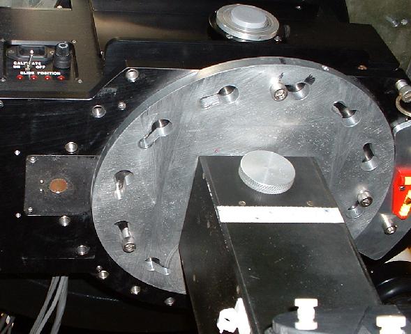
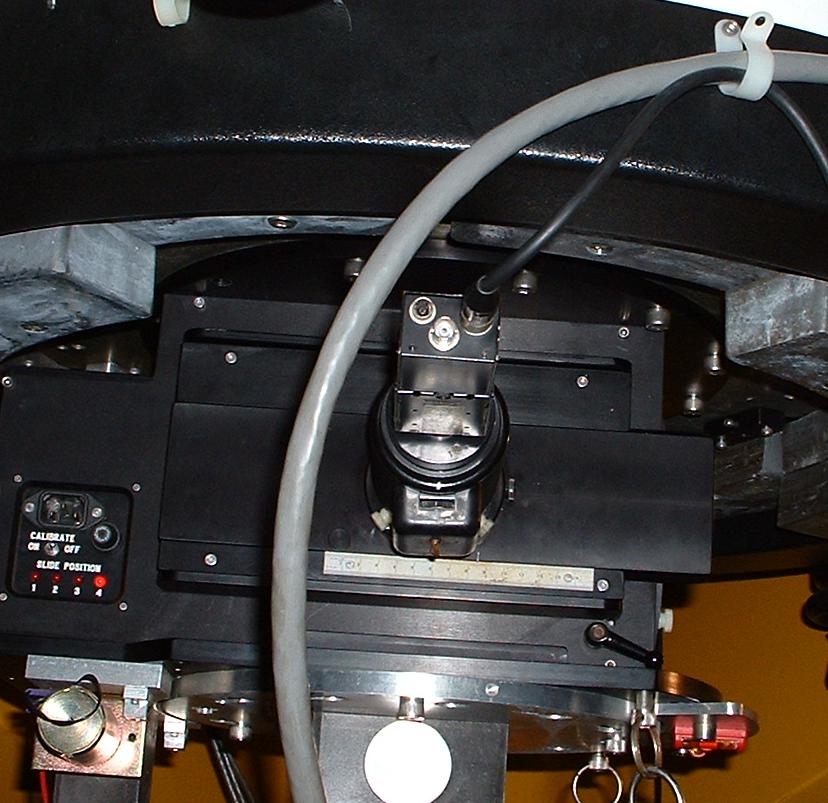
Mounting the Comparison Lamp
The comparison lamp usually resides on the telescope pier on top of the
comparison lamp power supply. Before this lamp is mounted beside
the spectrograph, a small penny-sized brass plug must be removed using
a screw driver from the base of the GAM (see figure above).
Once this is done the comparison lamp is mounted immediately to
the east of the spectrograph using the outer set of bolt holes (see
figure below). One cable from the lamp is permanently attached to
the power supply - make certain that it is can swing freely. The
other cable ends in a two pronged plug - it must be inserted into its
mate which will be above your head, hanging from the telescope.
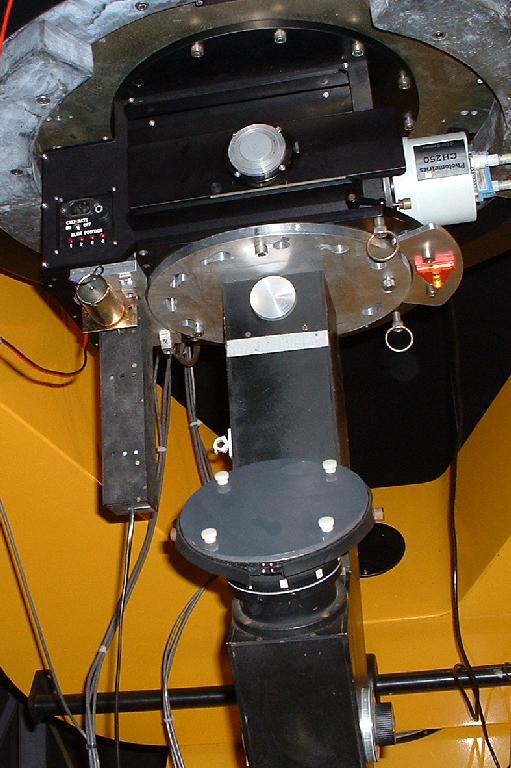
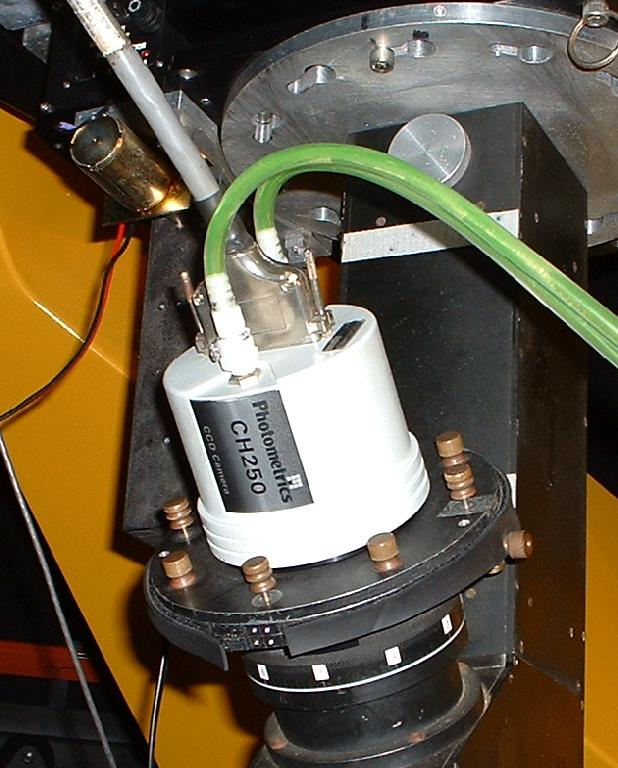
Mounting the CCD
The dust cover on the camera mount on the spectrograph may now be
removed. Remove the CCD from the west port of the GAM and backout
all the thumbscrews so that they do not stick out from the lower
surface
of the CCD flange. Position the CCD on the spectrograph camera
flange
so that the label (CH250) is facing north (see figure below). The
CCD shorting plug should be aligned EW. Align and tighten the
four
thumbscrews which are in the diagonal positions (these are not the set
used
for the filter wheel). Install the dust cover on the west port.
Now remove the blue shorting plug from the CCD and place it in a safe
place. Install the CCD cable to the CCD, and loop it over one of
the white plastic loops on the telescope so that it will not flop
around.
Once this is done, turn the power strip on the west side of the
pier
on. Check that the temperature on the CCD control box is going down.
Data Acquisition Computer Setup
The data acqusition computer in the control room is normally left
on. Turn on the monitor and click on the icon for PMIS.
This will open up a window with a black background. Under
"File", click on "New Image", and a square window (where the data will
appear) will open up with a white background. Back in the first
window, type at the prompt: ROI RECT 426 0 183 1024 . This will
draw a rectangular outline in the image window. Go to the image
window, and click on the ROI menu.
Click on "ROI to Camera". Nothing immediate will seem to
happen,
but once the first set of data is acquired, the window will shrink to
the
ROI (region of interest).
Power up the Comparison Lamp
The power strip that powers the CCD also powers the power supply
for the comparison lamp. The power supply resides on the
telescope pier below the polar axis. Push the red button and turn
the knob
until the current is at 15 mA. Do not under any circumstance
exceed
25mA! You should see a faint violet glow coming through the
ventilation
holes on the comparison lamp.
Telescope Setup
To set the telescope up for the nights work, follow the standard
procedure in the DSO User's Manual. Under the GAM setup, set the
slide (motor #1) to position 4. Check to make certain that the
LED
on the GAM is indeed on position 4. Once the telescope is fully
setup,
carry out the following steps:
In the spectrograph drawer in the control room (labeled "Gray") you
will find an old dark-brown 1 1/8" f.l. eyepiece, plus a brass
extension tube. Insert the eyepiece in the brass extension tube,
and then slide this tube into the aluminium 1 1/4" to 2" adapter that
has an off-axis hole. Tighten the two nylon screws, and then
insert the entire assembly into
the north port of the GAM so that the two nylon screws are at 45 degree
angles and are pointing "down", and tighten the retaining screw on the
GAM. The north port (which has a two-inch circular hole which
will accept the aluminum adapter) is on a drawer which can be pulled
out. Pull the drawer out so that the scale on the western side of
the drawer reads 2.0 cm. This drawer is released and locked with
a lever under the
RHS of the drawer. Make certain to lock this drawer once you have
it properly positioned.
TV Guide Camera and Guide Star Setup
Now you are ready to find a set star. Select a set star from
the table on the bulletin board in the warm room; the best set star is
one that is a little to the east of the meridian. Use the "select
library object" command under the Movement menu in TCS to move to this
star by typing in the library number for the star, hitting return,
answering
``No" and then entering 7 for ``slew". Make certain that ladders,
etc. are out of the way before you move the telescope! First
center
the set star in the finder scope. The finder scope has
illuminated
crosshairs. Move the star to the single crosshair, and then
center
it on the western-most of the double crosshairs. Uncover the
spectrograph
slit by pulling the plunger on the south side of the spectrograph out
so
that about 13 indentations are showing. Then, look through
the North Port GAM eyepiece (the one you inserted a few minutes
ago).
Center the out-of-focus image of the star (it will be out of focus if
the telescope was not used for spectroscopy the previous night; if it
was
used for spectroscopy, then the star will be in focus. It is best
to defocus it at this point) on the slit, and then push the
spectrograph
cover (decker) back, using the plunger so that the decker covers up the
ends
of the slit (if the star was originally out of focus, the exposed
length
of the slit should be roughly the same length as the diameter of the
out--of--focus
image of the star). When the slit decker is properly positioned,
there
should be about 8 indentations showing on the plunger.
Once you are satisfied the star is centered properly and the decker is
properly adjusted, remove the eyepiece and aluminum adapter from the
GAM and bring them into the control room. Remove the eyepiece and
brass tube from the adapter. Fetch the intensified TV camera from
the cabinet in the dome (it will be in a black suitcase), and bring it
into the control room. The video cable is wound up and is hung on
a nail on the outside wall of the control room, near to the telescope
pier. Plug this video
cable into the appropriate plug on the back of the intensified TV
camera
(it may be necessary to rotate the plug while applying gentle pressure
to
get it to engage). Then, remove the cover from the intensified TV
camera, and insert the front tube of the intensified TV camera into the
aluminum adapter, so that the box--like battery holder on the TV camera
is centered between the two nylon screws. Tighten the nylon
screws, and insert the whole assembly into the north port of the GAM,
making certain that you tighten the retaining screw as tightly as
possible. The two nylon
screws should be aligned as before with the eyepiece. Make
certain that the CCD part of the intensified TV camera is aligned
parallel with the
base of the mirror cell (see figure below). Using the thumb
rotary switch on the TVcamera, turn the TV camera on, and rotate the
rotary switch (the "gain") about half or one--third of a turn. I
usually loop the video cable over the same plastic clip that the CCD
cable is on.
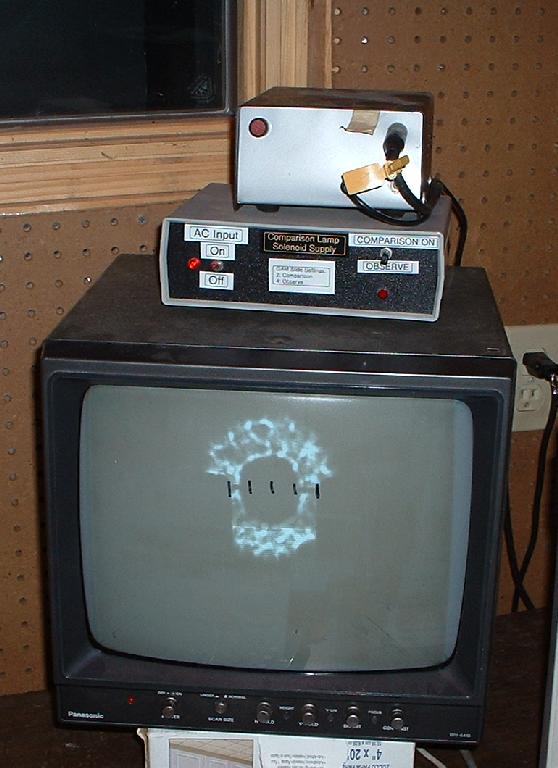
Go back into the control room, and turn on the TV monitor and the
intensified TV power supply (the power supply is a small metal project
box with a
push--button on the front. It is found on the top of the TV
monitor.
Push the button; it used to light up but doesn't any more - don't
push it twice! After a few seconds, if everything is okay, the
out--of--focus image of the star on the spectrograph slit should
appear on the screen
(see figure). If necessary, adjust the angle of the intensified
TV
camera on the telescope so that the slit on the TV screen is perfectly
horizontal. At this point, it is also a good idea to use a
marking
pen to make marks at the ends, center, and one quarter and three
quarter
points across the spectrograph slit on the TV screen. If there
are
marks from a previous night on the screen, and they are appropriately
place,
that is good - use them. If they are not properly placed, remove
them
with rubbing alcohol (there should be a bottle in the control room) and
remark
them (see fig below).
Since the set star is a bright star, we usually don't completely focus
it, as the in-focus image of the set star on the intensified TV can
damage
the TV phosphor. Focus this image so that it is about the size of
a quarter on the screen. Now center the out-of-focus image as
best
as possible, initialize the coordinates (using coordinates out of the
Bright Star Catalog or the Astronomical Almanac) for the set star
(using
the Initialization menu in TCS -- "2) Set Telescope Position''), and
then
find a fainter star (V about 6.0) near to the set star in the Bright
Star
Catalog, and slew to it (make certain ladders, etc. are out of the
way!)
You will see the dim, out-of-focus image of this star on the screen.
Use
the focus buttons (which can be sped up by pressing the middle "set''
button)
on the hand paddle until the star is in as good focus as
possible.
You may need to refocus from time-to-time during the night, as the
mirror
cools and comes to equilibrium. At this point, you can increase
the
gain on the TV camera to maximum if you plan to observe faint stars
during
the night. If you are only going to observe bright stars (< 6
mag),
leave the gain where it is.
Observing
Preliminaries
We now use a "macro" to assist in semi-automating exposures during
the night. To set this up, carry out the following steps.
Using Windows Explorer, make a new folder under drive E: (label
Gray) on the
data acquisition computer. This new folder should have a name
that
reflects the current date in the format mmmDDYY, for instance, jan2303,
sep1502, etc. The convention is to use the local date, not the UT
date.
Thus, if the night is Oct 15/16 2003, the name should be oct1503.
We
use this convention even if we start observing after local midnight.
In the main PMIS window (black background) click on the "Macro"
menu and select "Edit". Under the macro directory (on the C:
drive), enter the "Gray" folder, and then select "Specgrab.cmd".
About halfway down this macro you should edit the directory name
to that of the folder that you just created. Save the macro and
exit from the editor.
On the other Windows computer, click on the icon Fitsheader. This
runs a Visual Basic program that grabs info from the CCD camera and TCS
and uses that information to stuff the FITS headers in the datafiles.
You are now ready to turn to the first star of the evening.
However, it is best at this point to begin exposing a Dark.
In the data image window (white background), click on "Acquire"
and then on "Dark". Enter 300 seconds and expose.
While the Dark is exposing, enter the basic data
for the night into the header of the observing page for the night (blue
notebook), which will be in the observing briefcase. Note the sky
conditions, the grating used, the date (use the double-date convention,
i.e. Feb 10/11 2003), and your name and the name of any co-observers.
Now you can turn to the first star on your list. Slew to the
star, and spend a few seconds trying to get the star in the best
possible
focus using the buttons on the hand paddle. At this point, you
can
also go into the Rates menu in TCS (selection 3) and set the handpaddle
rates. I use 100 for the set rate, and 3 for the guide rate.
By this time the dark will have finished, and the dark will appear
in a new window on the computer screen. Click on "File" on
this new window and then "Export" and save the dark as a FITS file in
the
directory for the night. The name of the file should have the
format
dkXXXX.fit where XXXX is a running number. Check the previous
observing
night to find out what XXXX should be. Once you have exported the
Dark, take two Bias frames by selecting Bias from the Acquire menu.
Export these to the same directory as FITS files, using
biXXXX.fit as the format for the name. Again, XXXX stands for a
running bias number.
On the main data window (white background) click on the Display menu
and then click on "show cursor".
Acquisition of Stellar Spectra
Now center the star on the slit, using one of the marks that you
placed on the TV screen, and acquire a spectrum by using running the
macro that you just edited. This macro will prompt you for the
running
"PM" number and the name of the object. The standard exposure
time
built into this macro is 300 seconds. If the star is faint,
simply
guide the telescope so that the star remains at the same point on the
slit. If the star is bright, you will need to trail the star back
and forth along the slit. To do this, you can use the Trail
option under the Rates menu in TCS. A good trail rate is either 2
seconds or 5 seconds per second, and a good trail length between 10"
and 60", depending upon how bright the star is, and where you are
in the sky (the trail length
is multiplied by cos(delta), so you will need to use long trails near
the
pole to compensate). It will just take practice to know the
right trail length. The trail direction should be 90 degrees.
Once the spectrum has been acquired, the main data window will shrink
to the size of the ROI. You may wish to right click on the macro
to temporarily get out of the macro to resize the window. I
usually go into the Display menu, click on Zoom, and then click once on
the spectrum and then resize the spectrum window to nearly the full
length of the screen. Resize the window horizontally so that the
whole ROI width is visible. I usually also change the
scaling from "Optimal Scaling" to "Fixed Min/Max", setting about 1000
for the Min and then, maybe, 4000 for the Max. You may need to
change these settings for different stars. Alternately, you can
use "Dynamic Min/Max".
Now, check to make certain that the star was not overexposed. Run
the cursor up and down the spectrum. If no counts are above about
60000, the exposure was okay. For faint stars, you will want to
use the "Fixed Min/Max'' option, and enter appropriate values to scale
the image
so that the spectrum can be seen. You will need to experiment
with
the max value; for very faint stars, there may be only 100 or 200
counts in
the spectrum, hence a max value of 1200 may be appropriate. Use
your
cursor to find the approximate maximum number of counts in the
spectrum, and then set Max to about 20% above that value.
Unfortunately, these menu manipulations cannot be carried out
while the macro is running. However, counts can be read out once
the exposure is finished, even though the macro is running.
The macro automatically saves the exposure under a name with the format
PMXXXXX.fit where XXXXX is a running number. The macro will
automatically increment XXXXX if multiple exposures are taken.
It is good practice to take a number of exposures of the same star;
these exposures can be combined during the reduction process to
increase the signal to noise ratio. I almost always take at least
three spectra of any star, even bright stars. For fainter stars,
four is the minimum number, ranging up to twelve, all of the same 300
seconds. With stars that are not trailed, I usually move the star
to a different mark on the
TV screen between exposures so that the spectrum is not exposed on the
same part of the CCD every time. This helps to increase S/N as
well.
To end the macro once you are finished with a star, right click on
the macro after "starting" the exposure (the macro gives you two
seconds
to do this!).
You should aim for a minimum of about 10000 total counts in the
spectrum at the violet end - usually in the vicinity of the Ca II
K-line (this
will lead to S/N = 100, or 1% statistics). Measure the counts
near
to Ca II K in your first exposure of the star. Subtract about
1000
(the average number of counts in a dark) from these counts and multiply
by three (with good seeing an untrailed spectrum will be about 3 pixels
wide -- if broader, use that number of pixels in the multiplication).
Divide
this number into 10000. This is the minimum number of exposures
you
need for that star. Adhere to the minimum numbers mentioned above
(i.e. 3 for a bright, trailed star, 4 for a fainter untrailed star).
If
the foregoing calculation suggests the need for 10 or more spectra, you
will have to be content with S/N < 100, as other sources of noise
(read
noise, thermal noise in the dark, etc.) will dominate.
Comparison Spectra
Once you have completed the exposures for your star, it is
necessary to take a comparison spectrum before you move the telescope
to the next star. To accomplish this, move the GAM slide to
position 2 and then turn the comparison switch (located on the
comparison control box on top of
the TV monitor) from "observe" to "comparison" (make certain the other
switch
is set to "on" - it can remain there the entire night - see figure
above).
Using the spectrum window, acquire a comparison spectrum with an
exposure
of 1 sec. Export to the working directory for the night using a
name
of the format acXXXX .fit. Move the GAM slide back to position 4
and
set the switch to "observe". You are then ready to move to the
next
star.
Darks
You should try to take Dark exposures at least every hour, more
often at the beginning of the night while the CCD is still coming to
equilibrium. Try to get a minimum of 4 darks per night, a total
of 6 to 7 is preferable. After every dark, take two bias
exposures and export to the night's working directory. All darks
should have an exposure of 300sec.
Flats
It is not necessary to take Flat fields (flats) exposures every
night, as the flats are quite stable over time scales of weeks.
You
should take a set of flats every month. You can take a set of flats by
using the following procedure:
- If there is some other grating besides the blue 600 g/mm grating
in the spectrograph, it will be necessary to remove that grating and to
install blue 600 g/mm grating. The grating tilt should be 8o6'
(note that this is not the standard tilt for observing with the 600g/mm
grating).
For more information on how to remove and install gratings, see the
next
section.
- Move the GAM slide to position 1, and push the GAM drawer all the
way in.
- Uncover the slit so that the decker plunger shows about 13
indentations.
- In the spectrograph drawer, you will find a metal tube with a
diagonal mirror at the end of it. In addition, you will find a
white PVC tube with a toggle switch on the end. Push the PVC tube
over lens end of the brown 1 1/8'' eyepiece, and then put the combined
PVC tube/eyepiece assembly into the metal tube with diagonal, and
tighten using the set screw. Insert this entire assembly into the
North Port of the GAM, with the diagonal mirror facing down, i.e.
toward the spectrograph slit. You can gauge if the mirror is
properly aligned by centering the set screw between two screw heads on
the North Port of the GAM.
- In the spectrograph drawer, there is a little black Radio Shack
power supply. Plug this into the power box on the telescope tube, and
the other
end into the PVC tube. Turn the switch on. You should see
the PVC tube glowing dimly.
- Make certain that all lights in the dome are off. Expose
for 300ms
(milliseconds, not seconds!). To view the resulting flat, set the
scaling
on "Dynamic Min/Max'' and "Squeeze'' the frame until you can see the
entire frame. The flat will not be uniform, but it should be
symmetric from side to side (although not from top to bottom).
The maximum number of counts should be on the order of 20000, the
minimum (at the top edges) should be about 7000. If you are not
getting these counts, adjust the exposure accordingly. If the
flat is asymmetric from side to side, this can be corrected by rotating
the PVC/eyepiece/lamp assemblage in the North Port of the GAM.
- Take about 10 -- 15 flats, and export with the format
flXXXX.fit. You may need to turn back a number of pages in the
observing notebook to find the running number to use.
- At the end, do not forget to take a dark exposure with the same
exposure as the flat. Record this with the same format as the
normal dark
exposures: but with the prefix df: dfXXXX.fit.
- I usually take flats the last thing at night before I close down
and go home. If you leave the 600 g/mm grating in the
spectrograph with the
8o6' tilt, make a note of it so the next observer will
know that he/she will have to adjust or replace the grating before
observing.
Changing Gratings
There are currently two gratings (see Table 1) which are in common
use. These are the blue 1200 g/mm grating and the blue 600g/mm
grating. Both gratings use the same camera focus and tilt, so
those parameters will not need to be changed. To change a grating
and set the proper tilt, carry out the following steps with the
telescope pointed at the zenith:
- The gratings are stored in the plexiglass case in the
spectrograph drawer.
Except for the 1200 g/mm grating (which has a blackened handle) all
gratings
are marked on their ends with the grooves/mm, and the blaze
wavelength.
The blue 600 g/mm grating is marked with "600'' and "4000''.
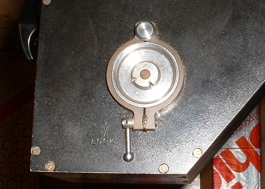
- A grating may be removed from the spectrograph as follows:
Grasp the black ``handle'' (not the graduated grating tilt knob!!) at
the base on the south side of the spectrograph and gently but firmly
turn it. The grating ``door'' should come off the spectrograph with
very little persuasion. The grating is held in a small ``drawer''
and is secured with a brass thumb screw. Loosen this screw, grasp
the grating handle (brass as
well) and pull the grating gently out of the drawer. (see figure
below)
- Remove the grating from the plexiglass box that you wish to
install in the spectrograph and replace it with the grating that you
just removed from the spectrograph. Holding the grating by the
brass handle, gently insert it in the grating drawer. It may take
a moment or two to get the angle right, but once the grating is in the
proper tracks, it will
slip right in; it will take no force to push it into the drawer.
Do Not use force in any part of this procedure! Tighten the brass
thumb screw and replace the grating door. Secure it by turning
the
black handle.
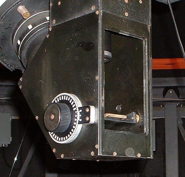
- The grating tilt must now be adjusted. This requires a bit
of black magic. Unlock the grating tilt mechanism (on the east
side of the spectrograph, there is a small brass lever -- see second
figure below.
Push this lever up as far as it will go). Use the graduated knob
on
the west side of the spectrograph to set the grating tilt recorded in
Table
1. Use the vernier scale to set the tilt accurately. Now it
is
necessary to carry out the fine adjustment of the tilt. This is
where
the black magic comes in.
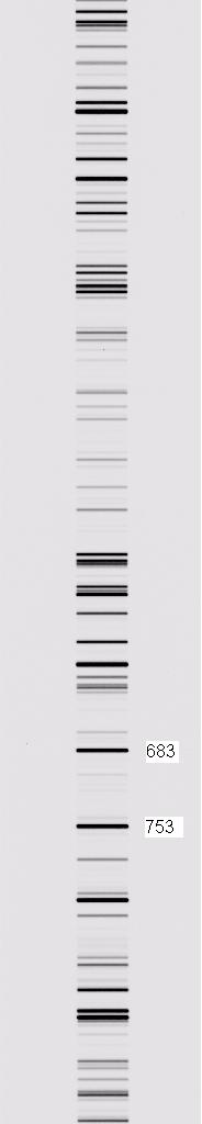
- Set up the comparison source as described in the main text, and
take an exposure of 1 second.
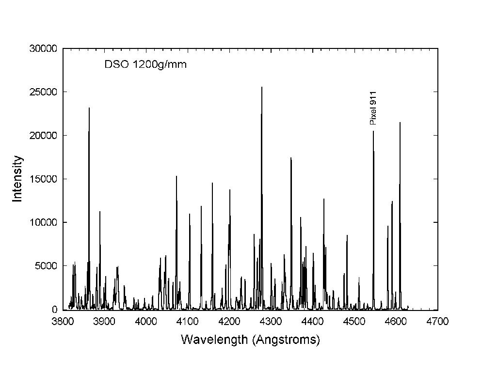
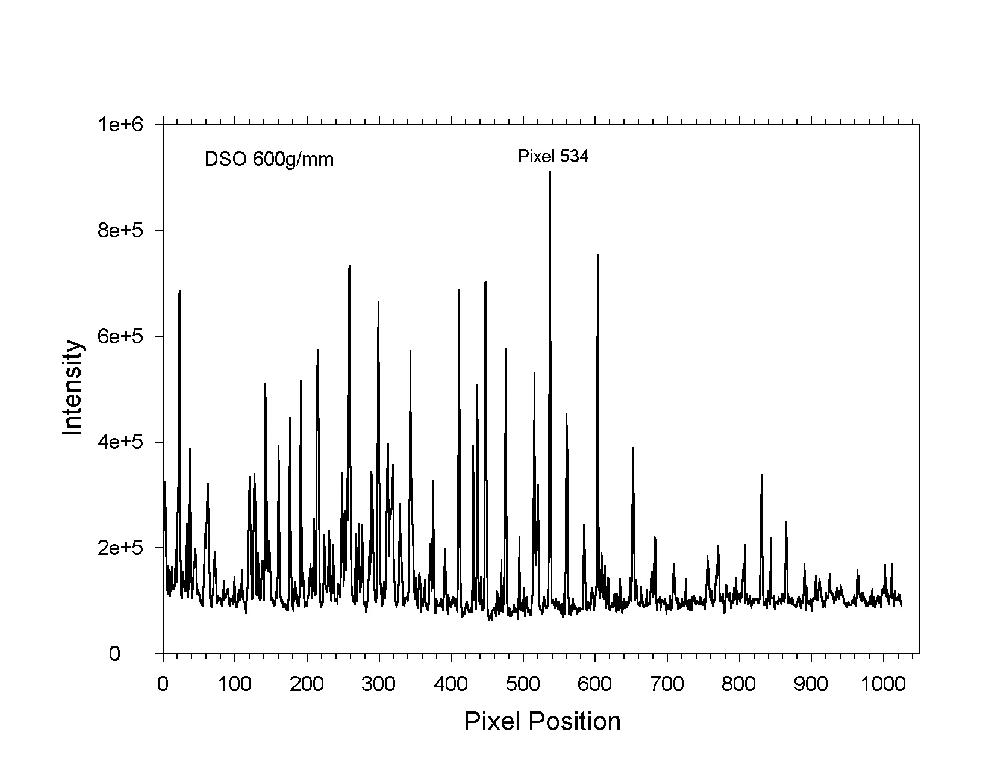
- At the front of the observing notebook and at the bottom of this
webpage, you will see two graphs of comparison spectra, one for the
1200 g/mm grating, the other for the 600 g/mm grating. Using the
appropriate graph, locate the indicated line on the exposure on the
screen. For instance, the indicated line on the graph for the
1200g/mm grating should be located at pixel 911. If the indicated
line is not at the designated pixel (you can determine this on the
screen if you select ``show cursor'' under the display menu') you
must change the tilt.
- Unfortunately, the graduated knob does not have a vernier motion,
and so, with the grating lever unlocked, lightly hold the knob, and
with just slight finger pressure rub your fingers over the knob in the
direction
you need the knob to turn. If you need to increase the pixel
number,
rub your fingers in the counter--clockwise direction, to decrease, in
the
clockwise direction. The knob should not visibly turn during this
process.
After doing this a few times, lock the grating, and take another
exposure. If you are doing things correctly, the position of the
line should have
changed, in the right direction, by 5 to 10 pixels. With a little
practice, it is possible to get the line to the exact pixel desired,
although
a leeway of +/- 5 pixels is acceptable. If the line is off by more than
about 50 pixels, it is not practical to change the tilt this way; try
to
use the vernier scale to get the knob closer to the recommended setting.
- Once you have the tilt within acceptable limits, lock the
grating, and
you are ready to go!
1000g/mm comparison (blue-violet, 2nd order)